
When applied to a piping system, ASME B31.1 (Power Piping Code) and ASME B31.3 (Process Piping Code) often seem interchangeable.
However, a closer examination reveals significant differences in their rules, applications, and guidelines.
This article outlines the key distinctions between ASME B31.1 and ASME B31.3, highlighting their respective scopes and implications.
1.0What is ASME B31.3 (Process Piping Code)?
ASME B31.3 provides comprehensive rules for designing piping systems used in:
- Petroleum refineries
- Onshore and offshore petroleum and natural gas production facilities
- Chemical, pharmaceutical, textile, paper, ore processing, semiconductor, and cryogenic plants
- Food and beverage processing facilities
- Related processing plants and terminals
Often referred to as the “Bible” for process piping professionals, ASME B31.3 dictates the design considerations of process plants, ensuring safe and efficient operations.
2.0What is ASME B31.1 (Power Piping Code)?
ASME B31.1 outlines the rules for piping systems typically found in:
- Electric power generating stations
- Industrial and institutional plants
- Geothermal heating systems
- Central and district heating and cooling systems
3.018 Major Differences Between ASME B31.3 and ASME B31.1.
ASME B31.1 is crucial for power piping professionals as it governs the design rules for power generation plants and systems that ensure reliability and safety in critical operations.
| Sr. No | Parameter | ASME B31.3-Process Piping | ASME B31.1-Power Piping |
| 1 | Scope (B31.3 vs B31.1) | ASME B31.3 provides rules for Process or Chemical Plant piping. | ASME B 31.1 provides rules for Power Plant piping. |
| 2 | Basic Allowable Material Stress | As per ASME B31.3, the basic allowable material stress value is higher (For example the allowable stress value for A 106 B material at 250 Deg C is 132117.328 Kpa as per ASME B 31.3) than the same as per B31.1. | The basic allowable material stress value as per ASME B31.1 is lower (For example the allowable stress value for A 106 B material at 250 Deg C is 117900.344 Kpa as per ASME B 31.1) than that of ASME B31.3. |
| 3 | Allowable Sagging (Sustained) | ASME B31.3 code does not specifically say about any limit of allowable sagging. An allowable sagging of up to 15 mm is acceptable in general. B31.3 does not provide a suggested support span. | ASME B31.1 clearly specifies the allowable sagging value as 2.5 mm. Table 121.5-1 of ASME B 31.1 provides a suggested support span. |
| 4 | SIF on Reducers | Process Piping Code ASME B31.3 does not use SIF (SIF=1.0) for reducer stress calculation | Power Piping code ASME B31.1 uses a maximum SIF of 2.0 for reducers while pipe stress calculation. |
| 5 | Factor of Safety | ASME B31.3 uses a factor of safety of 3; relatively lower than ASME B31.1. | ASME B31.1 uses a safety factor of 4 to have higher reliability as compared to Process plants |
| 6 | SIF for Butt Welded Joints | B31.3 uses a SIF of 1.0 for butt-welded joints | B31.1 uses a SIF of up to 1.9 max in stress calculation. |
| 7 | Approach towards SIF | ASME B31.3 uses a complex in-plane, out-of-plane SIF approach. | ASME B31.1 uses a simplified single SIF Approach. |
| 8 | Maximum values of Sc and Sh | As per the Process Piping code ASME B31.3, the maximum value of Sc and Sh are limited to 138 Mpa or 20 ksi. | For the Power piping code (ASME B31.1), the maximum value of Sc and Sh are 138 Mpa only if the minimum tensile strength of the material is 70 ksi (480 Mpa) otherwise it is dependent on the values provided in the mandatory Appendix A as per temperature. |
| 9 | Allowable Stress for Occasional Stresses | The allowable value of occasional stress as per ASME B31.3 is 1.33 times Sh | As per ASME B31.1, the allowable value of occasional stress is 1.15 to 1.20 times Sh |
| 10 | Equation for Pipe Wall Thickness Calculation | The equation for pipe wall thickness calculation in B31.3 is valid for t<D/6. | There is no such limitation in the Power Piping (ASME B31.1) wall thickness calculation. However, they add a limitation on maximum design pressure. |
| 11 | Section Modulus, Z for Sustained and Occasional Stresses | While Sustained and Occasional stress calculation, the Process Piping code ASME B31.3 reduces the thickness by corrosion and other allowances. | ASME B31.1 calculates the section modulus using nominal thickness. Thickness is not reduced by corrosion and other allowances. |
| 12 | Rules for material usage below -29 Deg. C | B31.3 provides extensive rules for the use of materials below -29 °C | The power piping code, B31.1, does not provide any such rules for pipe materials below -29 deg C. |
| 13 | Maximum Value of Cyclic Stress Range Factor | The maximum value of cyclic stress range factor, f as per B31.3 is 1.2. | As per ASME B31.1, the maximum value of f is 1.0 |
| 14 | Allowance for Pressure Temperature Variation | As per clause 302.2.4 of ASME B31.3, occasional pressure-temperature variation can exceed the allowable by (a) 33% for no more than 10 hours at any one time and no more than 100 hours/year or (b) 20% for no more than 50 hours at any one time and no more than 500 hours/year. | As per clause 102.2.4 of ASME B31.1, occasional pressure-temperature variation can exceed the allowable by (a) 15% if the event duration occurs for no more than 8 hours at any one time and not more than 800 hours/year, or (b) 20% if the event duration occurs for not more than 1 hour at any one time and not more than 80 hours/year |
| 15 | Design Life | Process Piping following ASME B31.3 is normally designed for 20 to 30 years of service life. | Power Piping using ASME B31.1 is generally designed for 40 years or more of service life. |
| 16 | PSV reaction force | B31.3 code does not provide specific equations for PSV reaction force calculation. | ASME B31.1 provides specific equations for PSV reaction force calculation. |
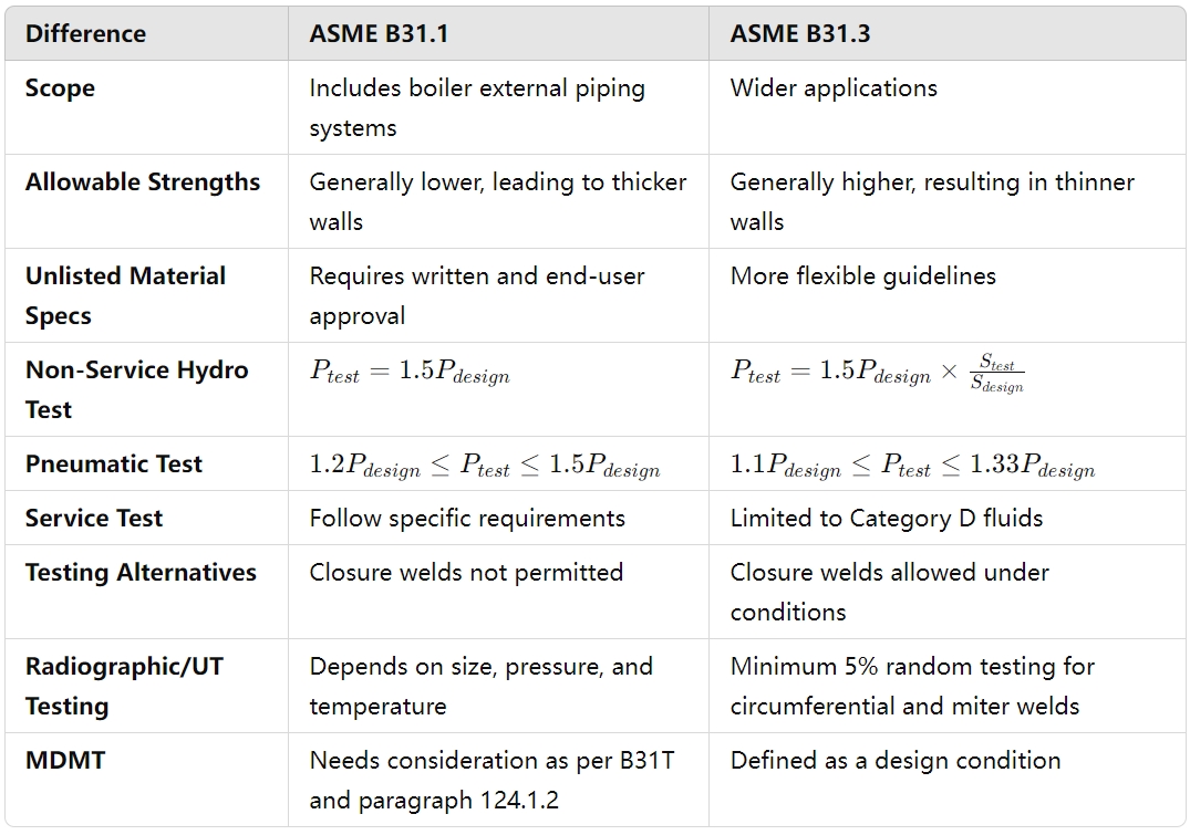
| 17 | Hydrostatic Test Pressure | As per ASME B31.3, the hydrostatic test for the piping system needs to be performed at 1.5 times the design pressure corrected for temperature, which means the design pressure must be multiplied by ST/S in the case of process piping. Here, ST=pipe material allowable stress at test temperature, and S=pipe material allowable stress at component design temperature. (Clause 345.4.2) | The hydrostatic test pressure following ASME B31.1 is 1.5 times the piping design pressure. (Clause 137.4.5) |
| 18 | Pneumatic Test Pressure | The pneumatic test pressure as per ASME B31.3 is (1.1 to 1.33) times the design pressure of the piping system. (Clause 345.5.4) | B31.1 instructs to use a pneumatic test pressure between (1.2 to 1.5) times the design pressure for the piping system. (Clause 137.5.5) |
4.0Simplified Differences Between ASME B31.3 and ASME B31.1
- Bending and Forming Requirements: The two codes have distinct guidelines for bending and forming operations.
- Welder and Brazer Qualifications: Qualification criteria differ between the two codes.
- Cast Iron Limitations: Each code sets different restrictions for using cast iron materials.
- Joint Types: Criteria for soldered, brazed, and threaded joints vary across the codes.
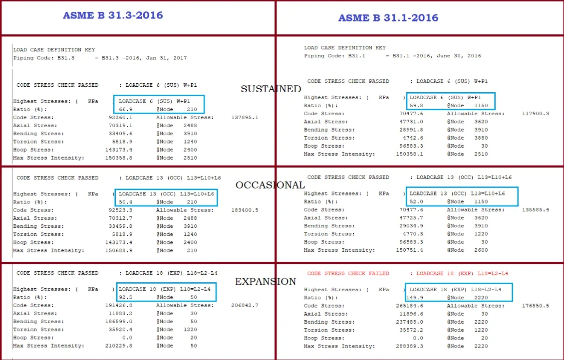
- Stress Variations: Stress values for the same system differ when analyzed using the two codes in software like Caesar II (Fig. 1).
5.0Differences in Calculation Formulas Among ASME B31.1, B31.3 Standards
References:
https://www.red-bag.com/engineering-guides/254-rb-eg-ue301-comparison-asme-b31-1-b31-3-and-b31-8.html
https://www.asme.org/learning-development/find-course/asme-b31-3-b31-1-practical-piping-design-process-power-applications/online–feb-10-14th–2025